Product Line

Frequently Asked Questions
Number of FAQs related to Sensors: 3
Expand AllCollapse All
-
The number of sensors that can be measured is determined by the sensor(s) and the datalogger(s). See the operator's manual for the sensor to determine the channels each sensor uses. The number of analog channels, pulse counting channels, switched excitation channels, digital ports, and continuous analog ports provided by each datalogger can be found in the small datalogger comparison chart and the large datalogger comparison chart.
-
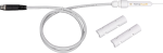
Whenever possible, purchase a sensor with the desired cable length. Some sensors have a user-specified cable length, whereas other sensors have a set cable length.
Sometimes, an old cable can be replaced with a new, longer cable.
Generally, additional cable cannot be spliced onto the existing cable because:
- Some sensor cables have bridge completion resistors at the pigtail end
- Some sensors are calibrated based on cable length
- Sometimes the color in the insulation is not the same as that visible at the pigtail end
- It is possible to introduce errors or malfunctions depending on the integrity of the splice
Splicing cable together increases the likelihood that water may enter the cable and cause shorting, corrosion, and some other potential issues, which in turn can cause measurement issues.
Because of the potential issues, do not splice any sensor cable without first contacting Campbell Scientific to discuss the sensor in detail.
-
Voltage Measurements
The effect of long cable lengths on analog measurements depends on the type of measurement that is made. For example, long lead lengths do not affect differential measurements of passive sensors (e.g., thermocouples, thermopiles, photo diodes), or active sensors that have a separate lead for the signal reference and the power ground, such as the CS106 Barometric Pressure Sensor. Making a differential measurement on an active sensor that shares the same lead for the signal reference and power ground (e.g., HMP60 Temperature and Relative Humidity Probe) does not eliminate the effects of long lead lengths.
So, what is the problem with long lead lengths? The problem is that when current flows through a ground wire, there is a voltage drop. The voltage drop follows Ohm’s law and causes an apparent voltage increase between the signal lead and the signal reference lead. This voltage drop occurs because wires have resistance. Long lengths of wire have more resistance than short lengths. Thus, long lengths of wire will cause a larger voltage drop than shorter lengths. Also, the voltage drop is more pronounced in active sensors (sensors that require 12 Vdc to operate) than in passive sensors, because there is more current flowing in the ground wires of the active sensors.
The HMP45C Temperature and Relative Humidity Probe draws approximately 4 mA at 12 Vdc when it is powered. The cable (p/n 9721) used in the HMP45C has a resistance of 27.7 W/1000 ft. For a Single-Ended Measurement (Instruction 1), the signal reference and the power ground are both connected to ground at the data logger; the effective resistance of those wires together is half of 27.7 W/1000 ft, or 13.9 W/1000 ft. Using Ohm’s law, the voltage drop, Vd, along the signal reference/power ground, is given by the equation below:
Vd = I * R
Vd = 4 mA * 13.9 ohm/1000 ft
= 55.6 mV/1000 ftThis voltage drop will raise the apparent temperature and relative humidity because the difference between the signal and signal reference lead, at the data logger, has increased by Vd. The approximate error in temperature and relative humidity is 0.56°C and 0.56% per 100 ft of cable length, respectively.
Since the HMP45C is fitted with both a wire for the signal reference and power ground, its output can be measured using a Differential Measurement (Instruction 2). The voltage drop, as described above, will not occur on the signal reference lead, because the data logger’s High and Low Analog Input Channels, used to make a differential measurement, are high impedance, i.e., no current can flow into them.
In general, use a Differential Measurement to measure sensors with long lead lengths. For sensors that require 12 Vdc to operate, use two separate leads for the signal reference and the power ground.
Bridge Measurement
The signal from bridge measurements suffers the same voltage drops when long lead lengths are used to connect the bridge to the data logger. (See the above section.) Again, a differential measurement, as used in the 4 Wire Half Bridge (Instruction 9) or 6 Wire Full Bridge (Instruction 9), can be used to eliminate this voltage drop. There are two additional complications in bridge measurements--the excitation voltage and the setting time.
Bridge measurements require that the data logger excite the bridge with a precision excitation voltage. When long lead lengths are used to connect the bridge to the data logger, the excitation voltage, at the bridge, will be less than the excitation voltage at the data logger. This voltage drop is caused by the resistance of the wires connecting the bridge to the data logger’s excitation channel. The excitation voltage drop can be compensated for by using a 3 Wire Half Bridge (Instruction 7), 4 Wire Half Bridge (Instruction 9), or 6 Wire Full Bridge (Instruction 9) measurement.
It takes a finite amount of time for the excitation voltage and signal voltage to stabilize to its true value. This time will vary with the lead length. For more information, see the "Effect of Sensor Lead Lengths on the Signal Settling Time" section in the data logger manuals (Section 13).
In general, if long lead lengths are required for bridge measurements, use the 3 or 4 Wire Half Bridge configuration over the 2 Wire and the 6 Wire Full Bridge configuration instead of the 4 Wire Full Bridge. See the "Bridge Resistance Measurements" section in the data logger manuals (Section 13).