This product is not available for new orders. We recommend ordering: CR1000X.
| Services Available | |
|---|---|
| Repair | Yes |
| Calibration | Yes |
| Free Support | No |
Overview
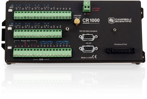
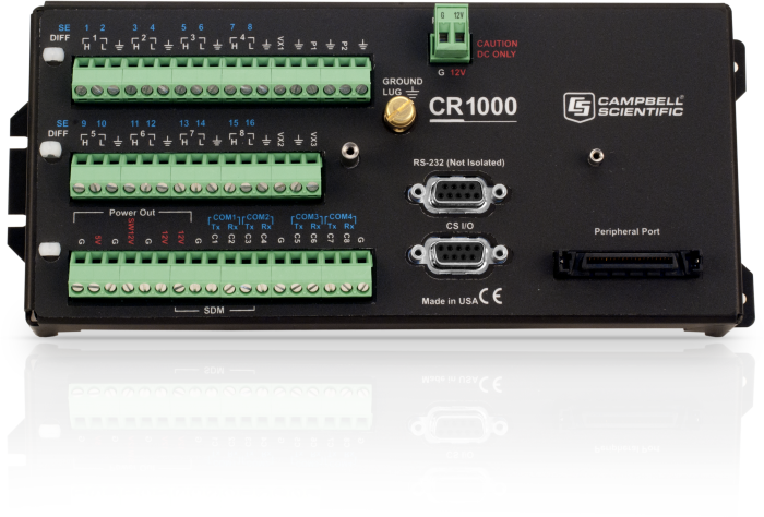
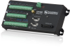
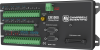
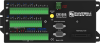
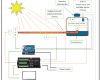
El CR1000 consiste en un modulo de almacenamiento y control CR1000M y el panel de alambrado CR1000WP. Este datalogger provee medicion de sensores, mantenedor del tiempo, reducion del tamaño del dato, almacenamiento de datos y programas y funciones de control. Los datos y los programas son almacenados en una memoria permanente y/o memoria RAM. Una bateria de litio respalda la memoria RAM y el reloj de tiempo real. El CR1000 se suspende automaticamente cuando su fuente de poder cae por debajo de los 9,6 V reduciendo la posibilidad de perdida de datos u obtener datos imprecisos. Al datalogger se le pueden conectar diferentes perifericos para aumentar su capacidad de memoria o para comunicarse con el remotamente.
El CR1000 se construyo con la base del CR10 y del CR10X, manteniendose la versatilidad de sus antesesores y mejorando algunas caracteriticas como un puerto RS-232, mas memoria de almacenamiento y mas puertos de comunicacion.
Cuando se utiliza en un sistema de adquision de datos (data-acquisition system) el CR1000 provee funciones de medicion y control. Un sistema completo incluye fuente de poder, caja hermetica, sensores, software de comunicacion y programacion y perifericos de comunicacion.
Benefits and Features
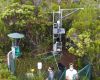
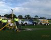
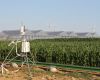
- Ideal applications include fire weather, mesonet systems, wind profiling, weather stations, air quality, ETo/agriculture, soil moisture, water level/stage, aquaculture, avalanche forecasting, time-domain reflectometry, vehicle testing, SCADA, and water quality
- Serial communications with serial sensors and devices supported via I/O port pairs
- Collects and stores data and controls peripherals as the brain of your system
- Flexible power and communication options make it ideal for remote locations.
- 4-MB memory can be expanded with add-on memory systems.
- Supports PakBus, Modbus, SDI-12, and DNP3 protocols
- Compatible with channel expansion peripherals allowing you to expand your system
- Program with LoggerNet, PC400, or Short Cut to fit your setup
- Communicates via various options: TCP/IP, email, FTP, web server.
- Gas Discharge Tube (GDT) protected inputs
- Battery-backed clock that ensures accurate time is maintained while data logger is disconnected from battery power
- Program and control on site with addition of CR1000KD keyboard and display unit.
- Contains custom ASIC chip that expands pulse count, control port, and serial communications capabilities
Images


3D/CAD Files:

Detailed Description
The CR1000 consists of a measurement and control module and a wiring panel. This datalogger uses an external keyboard/display and power supply. Low power consumption allows the CR1000 to operate for extended time periods on a battery recharged with a solar panel—eliminating the need for AC power. The CR1000 suspends execution when primary power drops below 9.6 V, reducing the possibility of inaccurate measurements.
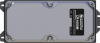
The CR1000's module measures sensors, drives direct communications and telecommunications, reduces data, controls external devices, and stores data and programs in on-board, non-volatile storage. The electronics are RF shielded and glitch protected by the sealed, stainless-steel canister. A battery-backed clock assures accurate timekeeping. The module can simultaneously provide measurement and communication functions. The on-board, BASIC-like programming language supports data processing and analysis routines.
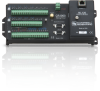
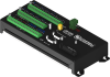
The CR1000WP is a black, anodized aluminum wiring panel that is compatible with all CR1000 modules. The wiring panel includes switchable 12 V, redistributed analog grounds (dispersed among analog channels rather than grouped), unpluggable terminal block for 12 V connections, gas-tube spark gaps, and 12 V supply on pin 8 to power our COM-series phone modems and other peripherals. The control module easily disconnects from the wiring panel allowing field replacement without rewiring the sensors.
Originally, the standard CR1000 had 2 MB of data/program storage, and an optional version, the CR1000-4M, had 4 MB of memory. In September 2007, the standard CR1000 started having 4 MB of memory, making the CR1000-4M obsolete. Dataloggers that have a module with a serial number greater than or equal to 11832 will have a 4 MB memory. The 4 MB dataloggers will also have a sticker on the canister stating “4M Memory”.
Compatibility
Please note: The following shows notable compatibility information. It is not a comprehensive list of all compatible products.
Measurement and Control
| Product | Compatible | Note |
|---|---|---|
| SDM-SIO2R |
Software
| Product | Compatible | Note |
|---|---|---|
| LoggerNet | Version 3.0 or higher | |
| PC200W (retired) | ||
| PC400 | Version 1.2 or higher | |
| PCONNECT (retired) | Version 3.1 or higher | |
| PCONNECTCE (retired) | Version 2.0 or higher | |
| RTDAQ | Version 1.0 or higher | |
| Short Cut | ||
| VISUALWEATHER - Retired (retired) | Version 2.0 or higher |
Additional Compatibility Information
Sensors
With several channel types, the CR1000 is compatible with nearly every available sensor, including thermocouples, SDI-12 sensors, and 4 to 20 mA sensors (via a terminal input module, such as the CURS100). A custom ASIC chip expands its pulse count, control port, and serial communications capabilities. The CR1000's I/O ports can be paired as transmit and receive, allowing serial communications with serial sensors and devices.
Measurement & Control Peripherals
The CR1000 is compatible with all of our CDMs (requires an SC-CPI), SDMs, multiplexers, vibrating-wire interfaces, terminal input modules, and relays.
Communications
The CR1000 communicates with a PC via direct connect, Ethernet interfaces, multidrop modems, short-haul modems, phone modems (land line, digital cellular, and voice-synthesized), RF telemetry, and satellite transmitters (Argos, Iridium, and Inmarsat).
Data can be viewed on the CR1000KD Keyboard Display, the CD100 Mountable Display with Keyboard, an iOS or Android device (requires LoggerLink), CD295 DataView II Display, or a user-supplied PDA (PConnect or PConnectCE software required).
Compatible external data storage devices are the CFM100, NL115, and SC115.
Enclosures
The CR1000 and its power supply can be housed in any of our standard enclosures.
Power
Any 12 Vdc source can power the CR1000 datalogger. Power supplies commonly used with the CR1000 are the BPALK, PS150, and PS200. The BPALK provides eight non-rechargeable D-cell alkaline batteries with a 7.5 Ah rating at 20°C.
Both the PS150 and PS200 consist of a sealed rechargeable 7 Ah battery and a charging regulator. Their battery should be connected to a charging source (either a wall charger or solar panel). These two power supplies differ in their charging regulator. The PS150 has a standard regulator and the PS200 has a micro-controller-based smart regulator. The PS200's regulator provides two-step constant voltage charging and temperature compensation that optimize battery charging and increases the battery’s life.
Also available are the BP12 and BP24 battery packs, which provide nominal ratings of 12 and 24 Ah, respectively. These batteries should be connected to a regulated charging source (e.g., a CH100 or CH200 connected to a unregulated solar panel or wall charger).
Software
CRBasic, the CR1000's full programming language, supports simple or complex programming and many onboard data reduction processes. Compatible software includes:
- Short Cut
- PC200W
- PC400 (version 1.2 or higher)
- LoggerNet (version 3.0 or higher)
- RTDAQ (version 1.0 or higher)
- PConnect (version 3.1 or higher)
- PConnectCE (version 2.0 or higher)
- VisualWeather (version 2.0 or higher)
Specifications
| -NOTE- | Additional specifications are listed in the CR1000 Specifications Sheet. |
| Operating Temperature Range |
|
| Analog Inputs | 16 single-ended or 8 differential (individually configured) |
| Pulse Counters | 2 |
| Voltage Excitation Terminals | 3 (VX1 to VX3) |
| Communications Ports |
|
| Switched 12 Volt | 1 terminal |
| Digital I/O |
|
| Input Limits | ±5 Vdc |
| Analog Voltage Accuracy | ±(0.06% of reading + offset) at 0° to 40°C |
| ADC | 13-bit |
| Power Requirements | 9.6 to 16 Vdc |
| Real-Time Clock Accuracy | ±3 min. per year (Correction via GPS optional.) |
| Internet Protocols | FTP, HTTP, XML, POP3, SMTP, Telnet, NTCIP, NTP |
| Communication Protocols | PakBus, Modbus, DNP3, SDI-12, SDM |
| Warranty | 3 years |
| Battery-backed SRAM for CPU Usage & Final Storage | 4 MB |
| Idle Current Drain, Average | < 1mA (@ 12 Vdc) |
| Active Current Drain, Average |
|
| Dimensions |
|
| Weight | 1.0 kg (2.1 lb) |
Documents
Product Brochures
Technical Papers
- Benefits of Input Reversal and Excitation Reversal for Voltage Measurements
- Preventing and Attacking Measurement Noise Problems
- Voltage Measurement Accuracy, Self-Calibration, and Ratiometric Measurements
- BACnet to Modbus Protocol Conversion (App. Note: 1M-C)
- Irrometer 950R1-O/950T Radio Network (App.Note: 3MI-F)
- AlphaGUARD Radon Monitor Interfaced with the CR1000 Datalogger
- Serial Sensors: Interfacing with CSI Dataloggers (App. Note Code: 2MI-V)
- CF Card Information (3SM-F)
Videos & Tutorials

 that allow programs to run on multiple data logger models. See how these extensions, combined with conditional compilation (#If, #Else, #EndIf, ElseIf), make it easy to write flexible CRBasic programs that work across different data loggers, even when they have different input ranges or terminal configurations.")


 Instruction
08:19 Summary")


")

 output sensors could be used.")


. This activity is helpful when troubleshooting.")

. A demonstration of one update method that uses a direct connection between a datalogger and a computer, and the Send OS Tab in the Device Configuration Utility.")

. A demonstration of one update method that uses File Control from the Connect screen. This method is suitable for a remote datalogger that is already deployed and could be on a telecommunications link, such as a cellular phone or an IP link.")

. Field maintenance tasks such as viewing and collecting data, setting the clock, and downloading programs are supported.")


Downloads
CR1000 OS v.32.07 (4.60 MB) 15-05-2024
Execution of this download installs the CR1000 Operating System and Compiler on your computer. It also updates the CR1000 support files for the CRBasic Editor.
Note: This OS has crossed the 2 Meg CR1000 size limit for remote download. The OS must be downloaded to the 2 Meg CR1000 via direct connect with the Device Configuration Utility. All OS download methods are supported by the 4 Meg CR1000.
Upgrading from versions prior to version 28 of the Operating System will reset the datalogger’s CPU drive. This is due to a change in the format of the file system from FAT16 to FAT32. In order for the datalogger to operate correctly, as part of the upgrade, the CPU drive is formatted to FAT32. Any programs stored and running from the CPU drive will be lost. It is not recommended to update the datalogger’s Operating System over a remote connection where program control regulates the communication equipment (turning it on or off, etc.). In these cases, an on-site visit and a backup using DevConfig’s backup utility is necessary to update the datalogger’s Operating System.
Watch the Video Tutorial: Sending an OS to a Local Datalogger.
In all cases where the datalogger is being updated from an Operating System prior to 28, the use of DevConfig’s backup utility is recommended due to the CPU drive being formatted using the new FAT32 format.
Device Configuration Utility v.2.35.02 (49.5 MB) 22-06-2026
A software utility used to download operating systems and set up Campbell Scientific hardware. Also will update PakBus Graph and the Network Planner if they have been installed previously by another Campbell Scientific software package.
Supported Operating Systems:
Windows 11 or 10 (Both 32 and 64 bit)
Frequently Asked Questions
Number of FAQs related to CR1000: 13
Expand AllCollapse All
-
Calibration of the CR1000 is recommended every three years.
-
The potential transformer and the current transformer provide differential outputs that have galvanic isolation from the voltage and current in the circuit they are measuring. However, there is no need to run the outputs of these transformers into differential inputs of the data logger and unnecessarily consume additional data logger channels. We conducted extensive testing for noise immunity, for inaccuracies from ground loops, and more before concluding that single-ended measurements in the ACPower() instruction have the same performance as differential measurements would provide. Please note that as a result of the galvanic isolation of the potential transformer and current transformer, the data logger ground is NOT connected to the ground of the circuit they are measuring.
Said differently, you can connect differential outputs of a sensor to single-ended inputs of the data logger. However, doing so creates the possibility of poor common-mode noise rejection in the data logger and the possibility of introducing inaccuracies from ground loops between the sensor and the data logger. Note that in this application, the transformer isolation of the potential transformer and the current transformer eliminates these concerns.
Simply connect one of the potential transformer secondary wires and one of the current transformer secondary wires to the data logger ground. Which wire in either case makes a difference, as the phase information allows the measurement of power flowing in either direction. If you measure negative real power when it should be positive, then reverse the secondary wires of the potential transformer where they connect to the data logger. Alternatively, you can reverse the secondary wires on the current transformer, but don't reverse both pairs of wires.
-
CR1000 dimensions with CFM100 or NL115 attached:
9.9 x 4.0 x 2.8 in.
25.2 x 10.2 x 7.1 cm -
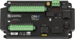
When idle, the CR1000, CR6, and CR1000X consume less than 1 mA @ 12Vdc. Similar to the CR6, the CR1000X has a much faster processor that requires more power when up and running. As such, there will be higher current draws during active measurements, serial communications, or when plugged into a PC via USB or Ethernet.
It may be helpful to think of the CR6 and CR1000X as being built on the same "platform."
-
Yes. The CR1000 is fully programmable to output alarms. The CR1000 can initiate telecommunications such as sending an e-mail or text message, providing audible voice-synthesized information, or calling a pager. The CR1000 can also activate physical alarms, such as sirens and strobes. In this type of installation, a relay device, such as the A6REL-12, is typically used to send a control signal to the alarm device.
-
A practical maximum is to connect one multiplexer per every two control terminals on the data logger. Control terminals can be shared between multiplexers to increase the number of connected multiplexers. Sharing terminals, however, requires more complex wiring and programming. Users who would like to connect more than one multiplexer per every two control terminals are advised to contact a sales or support engineer at Campbell Scientific for assistance.
-
Sending a serial string out one of the data logger COM ports requires at least two instructions. Generally, the SerialOpen() instruction is used to set the characteristics of the communications port, such as baud rate and error detection (for example, 115.2k, N, 8, 1). The instructions SerialOut() or SerialOutBlock() can be used to transmit a specified string. See the CRBasic Editor Help for examples of programs using each of these instructions.
-
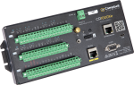
Although there are significant additions to the CR1000X program instructions that are not available in the CR1000, in most cases, you can load your program written for the CR1000 to a CR1000X with minor instruction changes. The most notable of the minor instruction changes is in the analog measurement instructions. For more information, see the "Replacing Your CR1000 Data Logger with a CR1000X: What You Should Know" blog article.
-
The CR1000 stores data in a binary format (1s and 0s), which is very compact. Campbell Scientific software, such as LoggerNet, collects the data in this binary format and converts it to a readable format such as ASCII. The CR1000 Status table contains information regarding how memory is allocated for data storage. This information can be accessed through the Station Status button on the LoggerNet Connect screen. The Table Fill Times tab lists the tables in the datalogger, along with the number of records in the table.
-
A free program generator for all Campbell Scientific data loggers is Short Cut for Windows (SCWin). Short Cut can be used to create programs in many situations where Campbell Scientific equipment is used.
In situations where program requirements are too complex or specialized for Short Cut, programs can be written in any text editor that can edit and save plain ASCII text. However, creating an error-free program would be very difficult. The CRBasic Editor that comes with PC400 and LoggerNet provides a programming environment with procedure templates, integrated help, programming examples, the ability to test compile the program before sending it, and many other features that can be very helpful when developing a program.
Casos de estudio

In Southern Idaho, the roads are often dirt, the bright blue sky is expansive, and......read more
Overview At Campbell Scientific, we are committed to supporting projects that harness technology to address real-world......read more
Tropical volcanic islands are biodiversity hotspots where the Critical Zone (CZ) remains poorly studied. In......read more
Severe Tropical Cyclone Debbie was a category 4 system that made landfall near Airlie Beach......read more

A spectacular fire destroyed three-quarters of the roof of the Basilica of Saint Donatian and......read more
PhénoField® is a unique, open-field research tool in Europe that allows researchers to understand how......read more

When Dennis Quaintance decided to build the Proximity Hotel in Greensboro, North Carolina, he knew......read more

CalWind Resources owns and operates a wind farm in Tehachapi, California. The wind farm has......read more
Articles and Press Releases
Newsletter Articles
- Case Study: North Carolina “Green” Hotel 18-10-2012
- Case Study: Florida Water Diversion Control 18-10-2012
- New Operating System for CR800, CR1000, CR3000 17-08-2012
- Case Study: Station Provides Flood Warning & Road Weather Data 17-08-2012
- Case Study: Researching Glacier Retreat in the Andes 17-08-2012
- Case Study: Water-Supply SCADA System 15-03-2012
- Case Study: Post-Tensioned, Fiber-Reinforced Bridge 16-11-2011