
Productos retirados


Fundamentals of Data Loggers
What is a datalogger?
A datalogger is a device used to record and store the output of one or more sensors. In some cases, the datalogger interprets the electical signal from the sensor and converts it to units. In cases where a smart sensor provides digital output, the datalogger simply records the data. Early dataloggers were strip chart recorders that recorded measurement data onto paper. Over time, dataloggers evolved to store data digitally on various types of media. Today, data is typically stored on modern flash memory and often transmitted via a variety of telemetry methods.
Note: Similar terms for "datalogger" include "data logger," "data recorder," "data acquisition system," and "RTU" (remote terminal unit). Which term is used often varies by industry or discipline.
Today, a wide range of devices are referred to as "dataloggers," and they can vary greatly in their functionality. For example, one datalogger may be packaged together with a sensor for a single application-specific purpose, such as measuring temperature. Another datalogger may be a general-purpose device that is used in many different applications to log data from multiple sensors of varying types.For the purpose of this discussion, our focus will be on general-purpose dataloggers.
Most modern, general-purpose dataloggers are microprocessor-controlled electronic devices that can interface directly with a variety of sensors to do the following:
- Provide measurements at specific time intervals
- Process statistical and mathematical data
- Store data
- Initiate a variety of telecommunications
- Transmit measurement data and calculated values
In addition to their measurement and monitoring functions, some dataloggers can trigger an alarm or notification, as well as control an external device, in response to any of the following: a specific, measured site condition; time of day; or event. For example, a datalogger may be programmed to respond to a measured rise in water level by closing a floodgate and sending a notification to personnel.
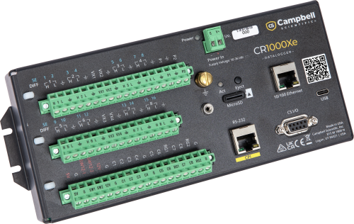
What are the different parts of a datalogger?
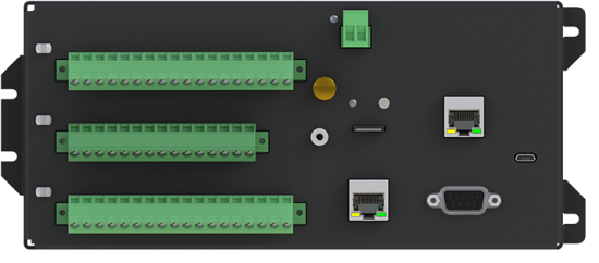
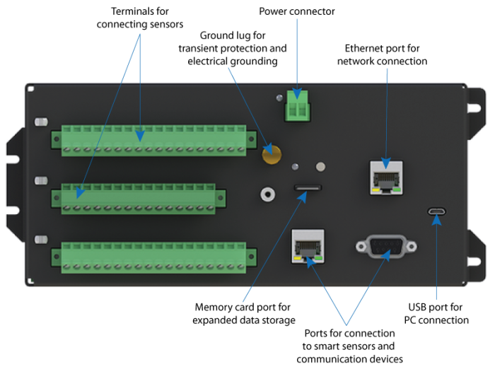
The following illustration depicts the most common parts of a general-purpose datalogger:
What is the role of a datalogger in a data acquisition system?
A data acquisition system consists of multiple electronic devices that act together to serve the primary purpose of collecting measured data. The general-purpose datalogger is often considered the brain of a data acquisition system, but it is only one of the interfaced components used in the process of acquiring, recording, transmitting, and analyzing measurements. These components may include the following:
- Sensors
- Datalogger
- Communications (data storage and retrieval)
- Software
- Power supply
- Enclosure and mounting equipment
A facility may individually select each of their data acquisition system’s components, thereby creating a customized solution that will meet their specific needs.
The datalogger can be programmed to scan the sensors of the data acquisition system repeatedly after a specified interval has passed (the scan rate), under specified conditions, or after the occurrence of a particular event type (such as rainfall). A sophisticated datalogger can receive the electrical signals from the sensors, perform any programmed calculations, convert the data as necessary to other units of measurement, and store the resultant data in the datalogger’s memory.
The datalogger’s acquired data and calculated values will need to be transferred to a PC or other device for increased access, sharing, analysis, and reporting. A variety of methods can be used to accomplish this, including communication peripherals with onsite and telecommunication options.
Where can dataloggers be used?
While many general-purpose dataloggers are designed to be installed in protected environments, some are specifically developed for extreme environmental conditions. These extreme environments include mountainous terrain, deserts, jungles, mines, oceans, and glaciers. A datalogger is typically left unattended for lengthy periods to automatically process and record measurement data from a variety of sensors until the monitoring period ends, which may be decades later.
The universal application of dataloggers in climates across the world, from the poles to the equator, is often attributed to their ruggedness, compact size, wide operating temperature ranges, low power usage, and capability of operating in diverse environments. The universality of sophisticated dataloggers is further enhanced by their many connection types and programmable inputs, which enable them to measure almost any commercially available sensor. Because dataloggers provide a comprehensive, accurate, and reliable depiction of the monitored conditions without the need for site visits, they are an indispensable tool for unattended, long-term monitoring and control for numerous industries and applications.
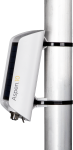
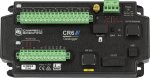
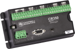
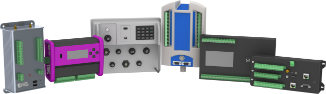
How do datalogger models differ from each other?
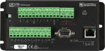
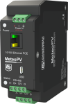
In this illustration, several different types of general-purpose dataloggers are displayed. These different types enable dataloggers to accommodate a wide variety of measurement applications.
While dataloggers can be compared and contrasted on many different levels, the following are some primary characteristics that may be helpful for you to be mindful of:
- Size
- Operating temperature range
- Variety and quantity of connection options
- Expansion capability
- Accuracy level
- Precision level
- Resolution level
- Scan rate and sample rate
- Communication capability
- Device control
- Programmability
- Onboard data processing
- Communication protocol
- Keyboard display
- Data storage
These characteristics are discussed briefly in the following sections.
Size
In general, the size of the datalogger is dictated by the number of inputs and outputs (I/O) and connection points. Smaller dataloggers have a smaller footprint requirement, which enables a facility to use a smaller enclosure that is less expensive and less noticeable. A smaller datalogger, however, is limited in functionality because fewer sensors or peripherals can be connected to it.
Even if a datalogger isn’t housed inside an enclosure, there may be space restrictions at the site that prohibit the use of a larger datalogger.
Operating temperature range
Although some manufacturers may not conform to this convention, the published operating temperature range typically refers to the range at which the datalogger will operate within its specified measurement accuracy. Measurements may still be recorded outside of this temperature range, but the accuracy of the measurement may be in question, and the datalogger may not perform as expected. Other operational errors may also occur.
Some dataloggers only have a standard operating temperature range, whereas other dataloggers may offer an extended temperature range option that is useful in environments with more extreme temperatures.
Variety and quantity of sensor connection options
The wiring panel of a datalogger provides terminals for connecting sensors. These terminals enable the datalogger to measure, communicate with, and power the sensors.
Dataloggers vary both in the quantity and types of input connections they offer. A datalogger with fewer sensor connection options:
- Provides a cost-effective option for a facility that requires only a few sensors to be connected to it
- Is limited in the amount and variety of data that it can collect from a single site
- May be limited to single-ended analog measurements only
- Is typically smaller and weighs less than a datalogger with more connection options
In contrast, a datalogger with more connection options:
- Is more cost-effective when many sensors are needed
- Is often modular and enables expansion of the data acquisition system through additional terminals or connections to measure more sensors, thereby satisfying the current application requirements and allowing for future growth
Some dataloggers can scan almost any sensor with an electrical response—whether the sensor’s signal output is voltage, current, pulse, digital, or serial. However, for the datalogger to interpret the sensor’s signal, the signal output from the sensor must be compatible with the datalogger input terminal to which it is connected. Typically, the instruction manual of a sensor provides information regarding which type of datalogger connection is required, as well as how to wire the sensor to the datalogger.
The following are some common terminal types used to connect dataloggers with sensors:
- Analog inputs
- Pulse counters
- Switched voltage excitation outputs
- Digital I/O ports
- RS-232, RS-422, or RS-485 ports
- 5 V terminals
- 12 V terminals
- Switched 12 V terminals
These terminal types are discussed briefly in the following sections.
Analog inputs
Analog inputs refer to both voltage and current inputs, and they are often used with any of the following:
- Bridge sensors
- Current outputs in 0 to 20 mA and 0 to 40 mA
- Platinum resistance thermometers (PRTs)
- Potentiometers
- Pressure transducers
- Resistive bridges
- Strain gages
- Thermistors
- Thermocouples
- Thermopiles
- Vibrating wires
- Voltage currents with shunt resistors
- Voltage outputs, including both single-ended and differential measurements
Pulse counters
Pulse counters are used by the datalogger to measure switch closures, low-level ac sine waves, or high-frequency pulses. Pulse counters sum the number of counts over each execution interval (scan rate), allowing variables such as rpm, velocity, flow, and rainfall intensity to be determined.
Pulse counters are often used with any of the following:
- Anemometers
- Contact closures
- Flow meters
- Tipping bucket rain gages
Switched voltage excitation outputs
Switched voltage excitation outputs are used with sensors that measure voltage resistance. These outputs provide programmable voltage excitation for resistive bridge measurements by switching the voltage on and off. The bridge measurements are the ratio of the voltage output to the excitation voltage, eliminating any errors in the excitation voltage.
Digital I/O ports
By default, digital I/O ports are configured as binary inputs to perform functions such as detecting status or reading SDM peripherals. In addition, each port can be individually programmed as a control output to physically control an external device.
RS-232, RS-422, and RS-485 ports
RS-232, RS-422, and RS-485 ports are used to connect the datalogger to smart serial sensors and communication devices.
5 V terminals
These terminals can be regulated or unregulated power sources for sensors and other peripheral devices.
12 V terminals
The 12 V terminal is generally used as an unregulated continuous power source for sensors and other devices.
Switched 12 V terminals
A switched 12 V terminal is used to power devices such as sensors that only require power periodically. These terminals are controlled by the datalogger to power the sensor only during measurements.
Variety and quantity of other connection options
The wiring panel of a datalogger also provides terminals for connecting power supplies, communication peripherals, and external control devices. The input and output connections on the wiring panel enable the datalogger to communicate with and power various peripherals.
The following are some common terminal types used to connect dataloggers with other peripherals:
- Continuous analog outputs
- Proprietary ports (often unique to the manufacturer)
- Removable power terminals
Continuous analog outputs
Continuous analog outputs provide voltage levels to peripheral devices or proportional controllers. This allows the datalogger to have control over other devices, including digital displays and controlled devices such as proportionally controlled gates.
Dataloggers often are used as measurement devices within a SCADA (supervisory control and data acquisition) system. The continuous analog outputs can then be used to send data directly from the datalogger to a PLC (programmable logic controller).
Proprietary ports
These ports are used to communicate with other expansion devices that are unique to the specific manufacturer.
Removable power terminals
These terminals are used to connect the datalogger to an external power supply. Because these terminals can be easily removed, they provide a quick-disconnect option.
Expansion capability
A datalogger may allow the expansion of its input and output capabilities using expansion modules, such as Synchronous Devices for Measurement (SDMs), and multiplexers. These add-on modules and multiplexers enable the datalogger to measure more sensors by increasing the number and type of connections available beyond what the datalogger provides on the wiring panel. Control modules increase the number of devices that can be controlled by the datalogger.
Accuracy level
Accuracy is the ability of a measurement to provide a result that is as close as possible to the actual value. For example, a datalogger that produces a measurement within ±0.1 of the actual value is said to be more accurate than a datalogger that produces a measurement within ±0.5 of the actual value. Accuracy is often listed by the manufacturer at a specific temperature (typically 25°C). Some manufacturers will specify accuracy over a temperature range.
Precision level
Precision is the amount of agreement between repeated measurements of the same quantity. For example, a datalogger that produces 10 measurements of the same sample within ±0.1 of each other is said to be more precise than a datalogger that produces 10 measurements of the same sample within ±0.8 of each other.
Resolution level
In measurements, resolution refers to the smallest change in a quantity that can be detected. For example, if one datalogger detects a difference to the nearest tenth of a millivolt, that datalogger is said to have higher resolution than another datalogger that detects a difference to the nearest whole millivolt.
Scan rate and sample rate
Depending on the manufacturer, some dataloggers cannot differentiate between the interval at which they scan (measure) the sensor and the interval at which they record the measured value. (The two rates are treated as being the same.) The datalogger will scan the sensor based on a selected record interval, and every measured parameter is recorded with each scan.
In contrast, a sophisticated datalogger can be programmed to scan a sensor based on a time scan rate, under specified conditions, or in response to an event. Programmed scan rates can vary greatly, depending on the datalogger model, and may range, for example, from once every few hours to 100,000 times per second (Hz). It is important to note that every single measurement from the scans does not need to be recorded. For example, if a sensor is scanned every five seconds (the scan rate), only an average reading for a 15-minute period (the sample rate) may need to be recorded.
The maximum scan rate is the highest frequency at which the datalogger scans the sensors. For example, dataloggers may range from a maximum scan rate of 1 to 100,000 Hz.
A datalogger with a slower maximum scan rate may be less expensive, but the rate at which parameters (such as rainfall) can be measured and recorded is limited. Consequently, less measurement data is available for a specified period compared to the amount of data that could be acquired during the same period using a datalogger with a faster maximum scan rate.
Communication capability
To transfer data from a datalogger to a central location, such as a base station PC or cloud-hosted database, a datalogger may have integrated communication capabilities, or it may be able to interface with an external communication device. These devices may support a hardwired connection (such as Ethernet), wireless cellular, or Wi-Fi. Various other communication options such as satellite or frequency-hopping spread-spectrum radios are also used.
Device control
A datalogger may be equipped to control external devices—in addition to providing advanced measurement and monitoring capabilities. As a control mechanism, a datalogger can be programmed to activate a device at a preset time, in response to a measured condition, or in response to an event. Dataloggers can activate or shut down motors, gates, pumps, purifiers, valves, injectors, etc. For example, if a temperature level rises above a predetermined maximum, the system can activate HVAC equipment. Moreover, control functions can be based on multiple conditions or events, such as deciding to initiate or suspend air exchange based on time of day, outside temperature, and/or inside temperature.
Programmability
Some dataloggers offer very limited programming flexibility such that the user is restricted to preset functions that the datalogger can handle. Other dataloggers use a microprocessor with a built-in programming language and instructions to enable the user to create and run new, customized programs. These dataloggers offer the user more control and the possibility to program cross-channel computations. The following is an example snippet of code from a datalogger’s programming language:
'Declare Variables and Units
Public BattV
Public PTemp_C
Public Temp_C

Units BattV=Volts
Units PTemp_C=Deg C
Units Temp_C=Deg C

'Define Data Tables
DataTable(OneMin,True,-1)
	DataInterval(0,1,Min,10)
	Average(1,Temp_C,FP2,False)
EndTable

'Main Program
Begin Prog
	'Main Scan
	Scan(1,Sec,1,0)
		'Datalogger Battery Voltage measurement 'BattV'
		Battery(BattV)
		'Datalogger Panel Temperature measurement 'PTemp_C'
		PanelTemp(PTemp_C,60)
		'Type T (copper-constantan) Thermocouple measurements 'Temp_C'
		TCDiff(Temp_C,1,mv34,1,TypeT,PTemp_C,True,0,60,1,0)
		'Call Data Tables and Store Data
		CallTable OneMin
	NextScan
EndProg
Onboard data processing
Some dataloggers can perform basic processing of the data collected from the system’s sensors. Examples include the calculations of daily minimums, maximums, averages, totals, or other statistical values. Moreover, parameters such as the following can be calculated using the data provided by sensors: density altitude, dew point, evapotranspiration, heat index, and wind chill.
By providing onsite statistical and mathematical processing, the datalogger can record just the calculated values rather than all the individual measurements. This provides the needed information in fewer numbers, simplifying the data analysis or review process. Because the frequency of recorded measurements is decreased, the quantity of data stored is reduced significantly. By reducing your quantity of stored data, you can prolong the time before your datalogger’s memory becomes full and needs to be downloaded, as well as decrease the amount of data that is being transmitted via the cellular or other wireless communication devices.
Communication protocol
The communication protocol is the system of rules that manages how data is exchanged between the datalogger and other devices. This includes communication between the datalogger and external measurement devices within the data acquisition system, between the datalogger and other dataloggers within a network, and between the datalogger and the PC or server. The protocol is particularly important when integrating a datalogger with an existing system to ensure that the system devices and the datalogger can all use the same protocol to communicate with each other. The communication protocols may be proprietary to the manufacturer of the datalogger, external devices, or software. These protocols may also be developed and managed by third-party organizations such as Modbus, DNP3, SDI-12, or FTP.
Keyboard display
Some dataloggers have an integrated or detachable keyboard display that includes a screen and keypad. The display enables the user to view measured data, generally in both real-time and historical formats.
The keypad functions of the display may also provide the user with the ability to program, configure, and analyze the datalogger while in the field—without the need for other external communication devices such as laptop computers, smartphones, or tablets.
Data storage
Knowing how frequently the sensors are scanned (scan rate), as well as how frequently data measurements and/or calculated values are recorded (sample rate), provides helpful information in determining how long a datalogger can record data before the memory capacity becomes full and requires downloading. Unless the datalogger has a display screen, data that is stored in the internal memory of the datalogger must be physically transferred to a PC or other web-browser-enabled device for visualization, analysis, sharing, report generation, and permanent storage.
The internal data memory, program, communications, and operating systems are stored in SRAM or RAM memory. Depending on the type of memory storage used, this memory is backed up by an internal lithium battery. In the event of power loss or when the datalogger is not connected to an external power supply, the battery maintains the memory and clock.
If a datalogger’s memory capacity is not sufficient to meet a facility’s scan rate and sample rate needs, an external data storage device may be purchased and used as well. Using an external data storage device provides a redundant data resource if the memory on the datalogger becomes full, resulting in data loss.
How do you select the datalogger model that is right for your application?
Selecting a datalogger is an important decision that requires careful consideration. For assistance with the selection process, review the detailed Purchase Considerations section.
Frequently Asked Questions
Number of FAQs related to Data Loggers: 1
-
The official definition of SDI-12 is Serial Data Interface at 1200 baud. Having stated that, SDI-12 is a protocol that was developed within the water resources field to make it easier to determine if a sensor and a datalogger were compatible. Instead of having to work through the specifications of the datalogger and the sensor for output, input, excitation, wiring, power, programming, etc., all SDI-12 sensors would have just three wires—a serial data line, a ground line, and a 12 V power line.